The Racor CCV Crankcase Ventilation Filter System will not allow crankcase emissions to be released into the atmosphere when installed in a closed system. This is
accomplished by filtering the blow-by gas and directing it into the engine air intake system.
The crankcase emissions flowing out of the engine breather are directed into the inlet
of the CCV and through the pressure regulator/by-pass valve. The regulator is integral to the head assembly and located up stream of the filter element so that the pressure remains
constant as the filter becomes restricted. The gases then flow in the inside-out direction through the filter, out of the unit and into the engine intake system usually between the air
filter and turbocharger.
The regulator valve, located in the head assembly, has two springs which maintain the valve in a static open position. Under dynamic conditions, the upper
spring force also determines the maximum crankcase open position and the maximum crankcase pressure allowed before by-pass occurs. The lower spring force maintains constant crankcase
pressure under changing inlet restrictions and crankcase flows. As negative pressure from the intake restriction is applied to the outlet of the CCV, the diaphragm valve is pulled 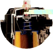 down. This downward movement
of the valve under intake restriction allows the valve to limit the maximum amount of vacuum that can be applied to the crankcase. Conversely, as crankcase pressure increases,
the valve moves away from the seat allowing more crankcase gas to flow through the filter. When the filter becomes severely restricted through time in service, the crankcase
pressure will increase to a predetermined value causing the diaphragm valve to move upward into by-pass position which limits the
maximum crankcase pressure that can be generated. An indicator located in the top cover of the assembly registers when the unit is operating in by-pass mode
and the filter element must be replaced. down. This downward movement
of the valve under intake restriction allows the valve to limit the maximum amount of vacuum that can be applied to the crankcase. Conversely, as crankcase pressure increases,
the valve moves away from the seat allowing more crankcase gas to flow through the filter. When the filter becomes severely restricted through time in service, the crankcase
pressure will increase to a predetermined value causing the diaphragm valve to move upward into by-pass position which limits the
maximum crankcase pressure that can be generated. An indicator located in the top cover of the assembly registers when the unit is operating in by-pass mode
and the filter element must be replaced.
The filter is a high-performance, microglass fiber, depth-loading, coalescing
media. Oil mist is removed from the crankcase emissions and flows down to the sump area of the filter housing. A drain in the sump allows the collected oil to be
returned to the engine crankcase. A check valve provided at the connection to the crankcase prevents gas flow or oil from bypassing the filter through the drain
line. Oil drain is accomplished when the column of oil in the drain line overcomes the differential pressure between the filter housing and crankcase - or when the engine is shutdown.
|